The Building

Building pre-intervention

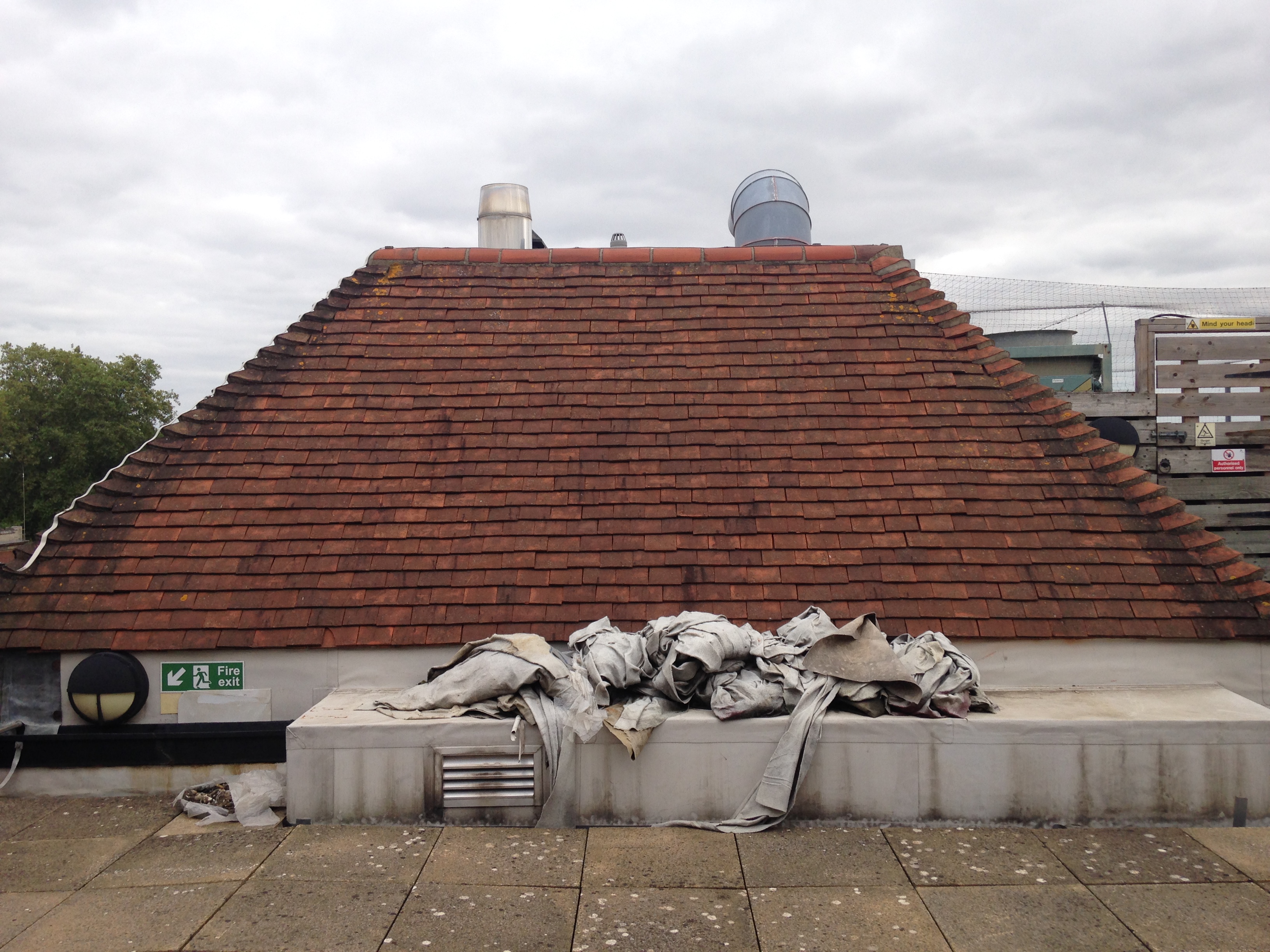
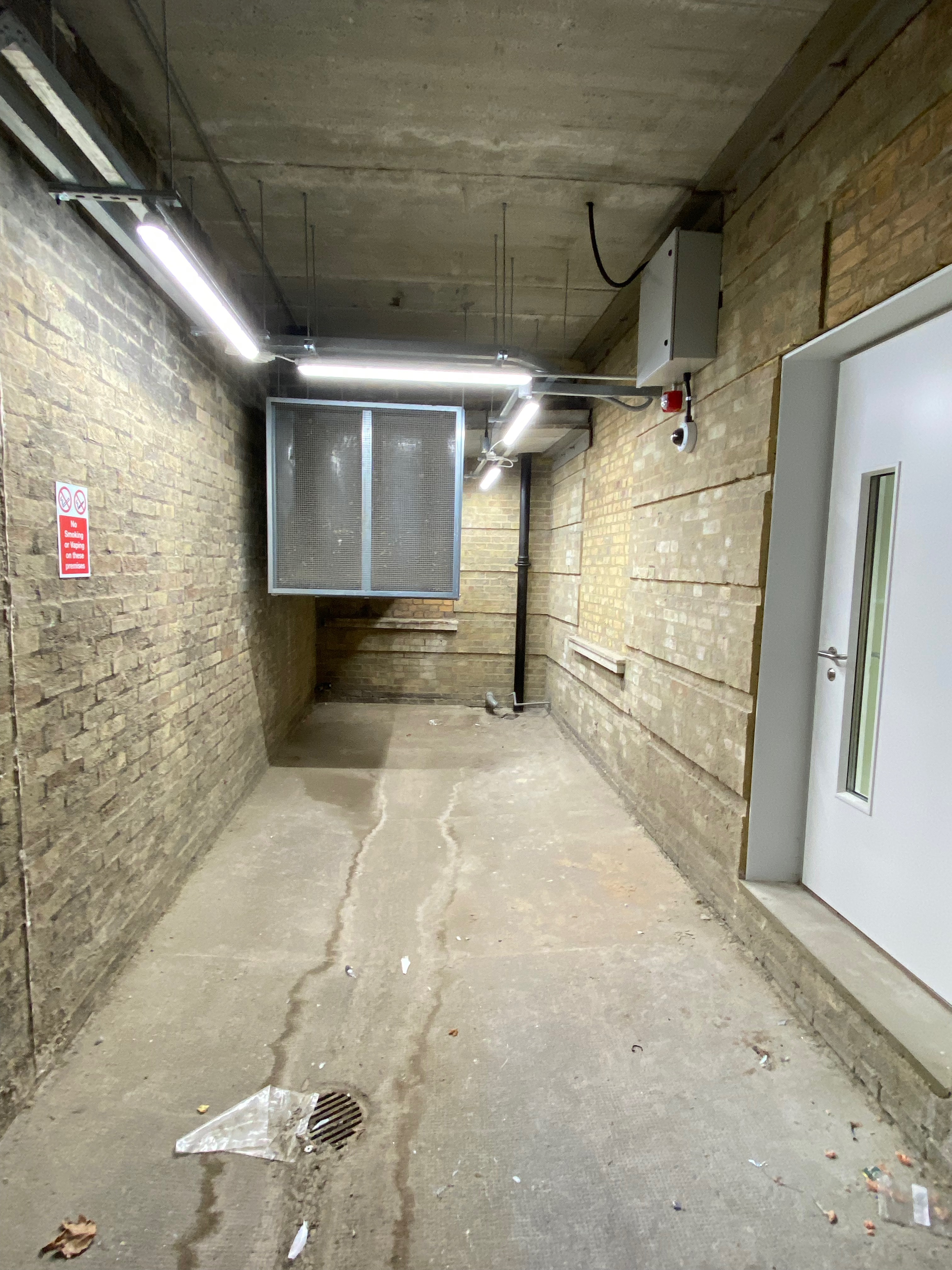
Building pre-intervention: IMG_3008.JPG.jpg
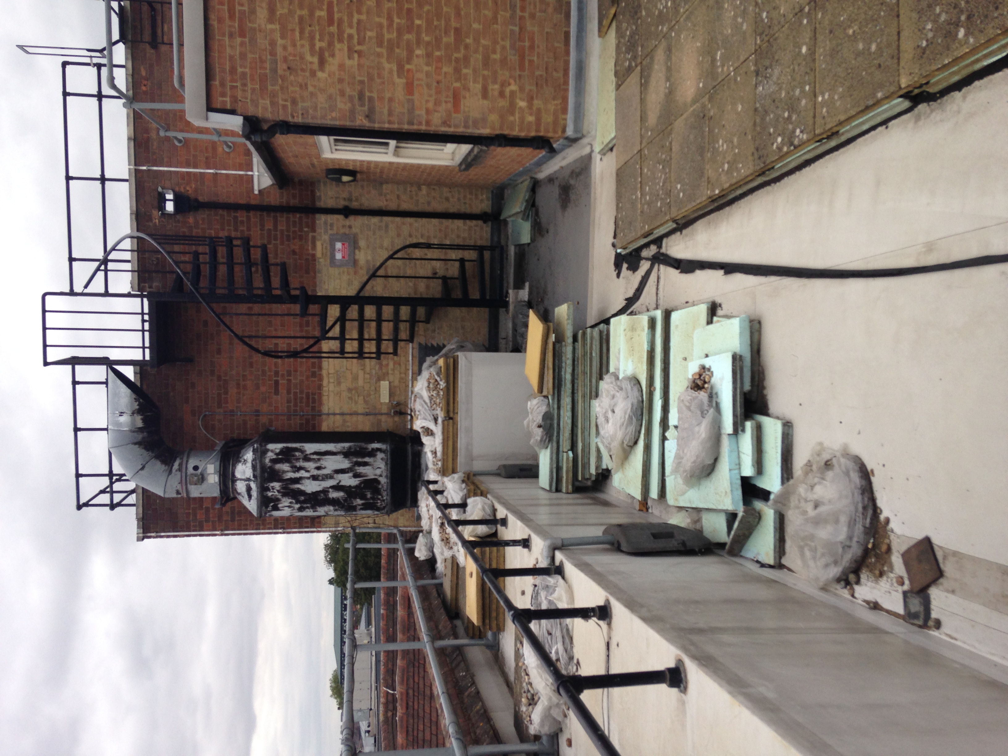
Building pre-intervention: IMG_3011.JPG.jpg
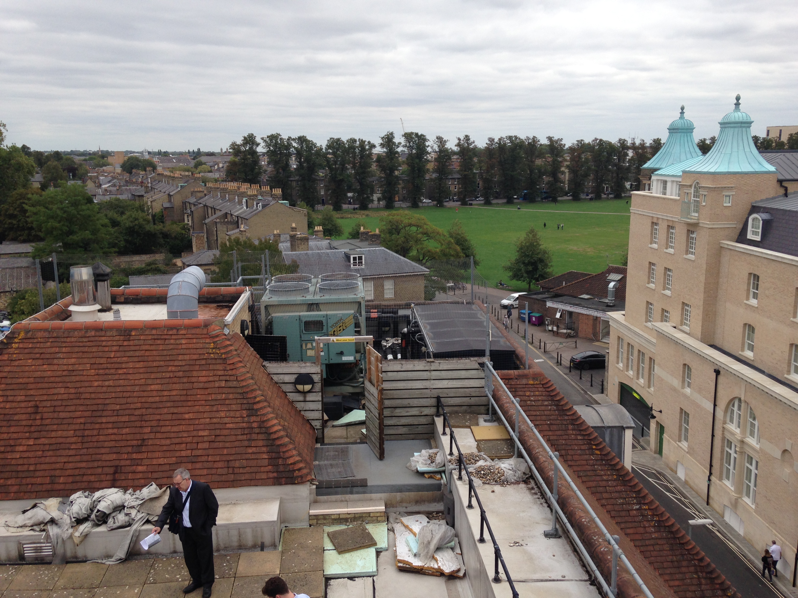
Building pre-intervention: IMG_3020.JPG.jpg

Building post-intervention

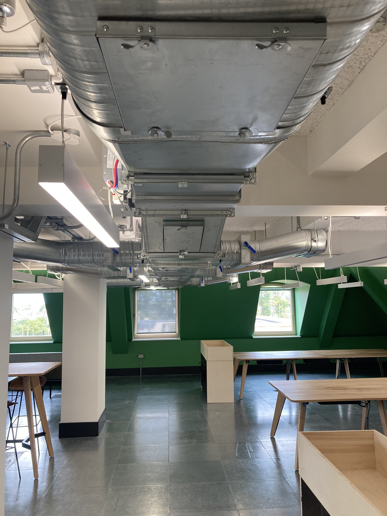
Building post-intervention: Ductwork.JPEG.jpeg
Building post-intervention: GeneralVent.JPEG.jpeg
Building post-intervention: IMG_4957.jpeg
Building post-intervention: IMG_8288.jpeg
Building post-intervention: IMG_8292.jpeg

Entopia Building

Entopia is an internationally leading, fabric first, sustainable retrofit of a 1930s, five-storey concrete frame structure with a basement located in a local conservation area in the historic Cambridge city centre. Entopia demonstrates that a ‘deep green’ retrofit can be delivered at a cost that is competitive to a conventional office refurbishment. The project started in 2019 and was completed in 2022.
The Solution

Solution pre-intervention

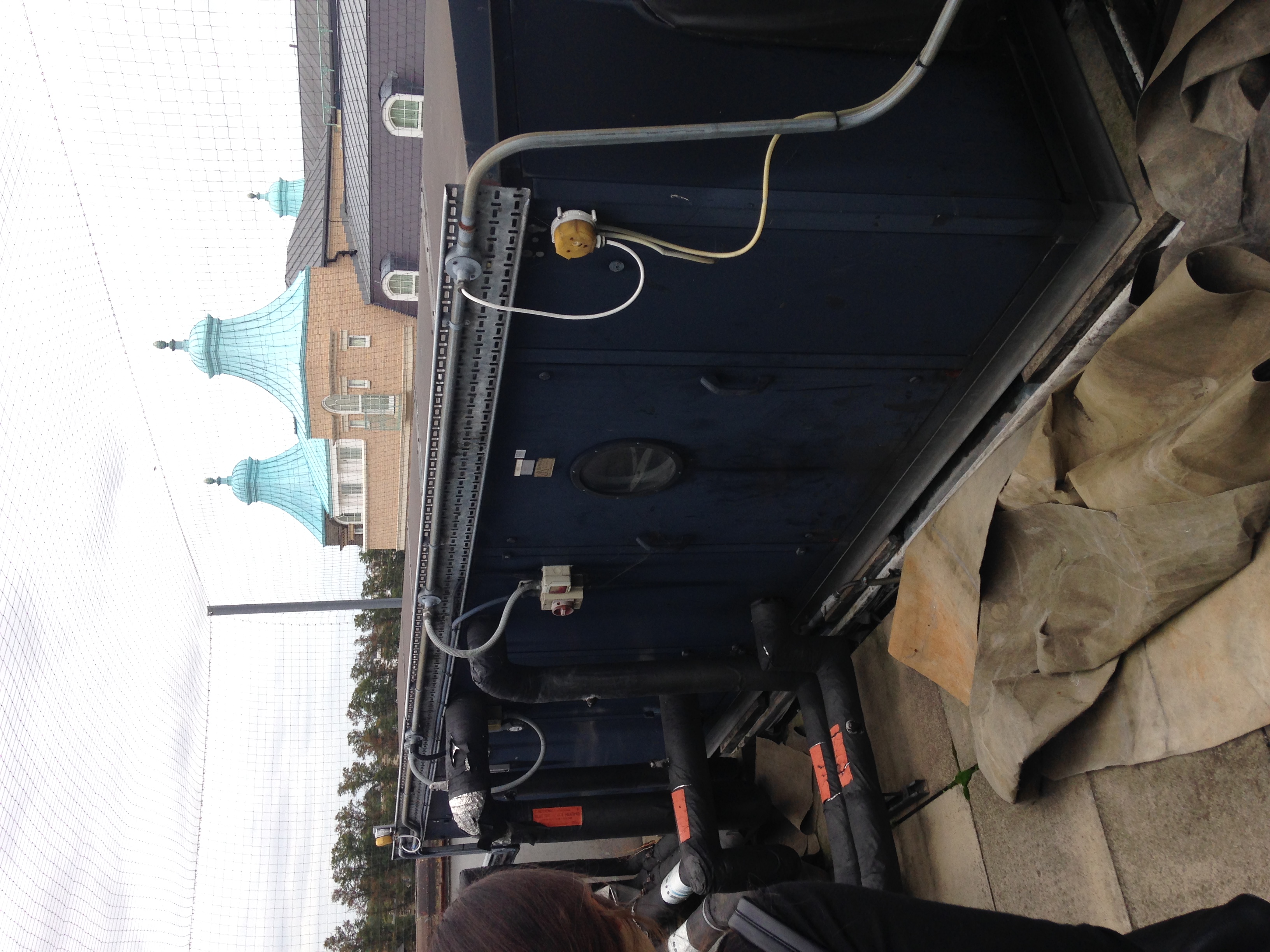
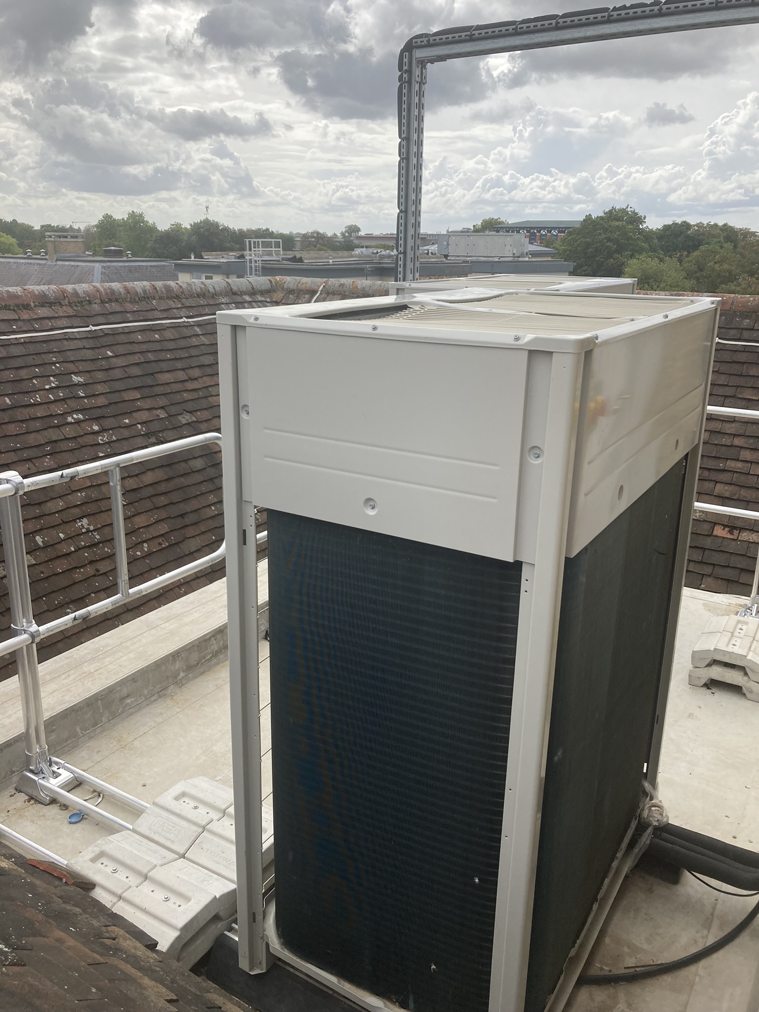
Solution pre-intervention: CondensingUnit.JPEG.jpeg
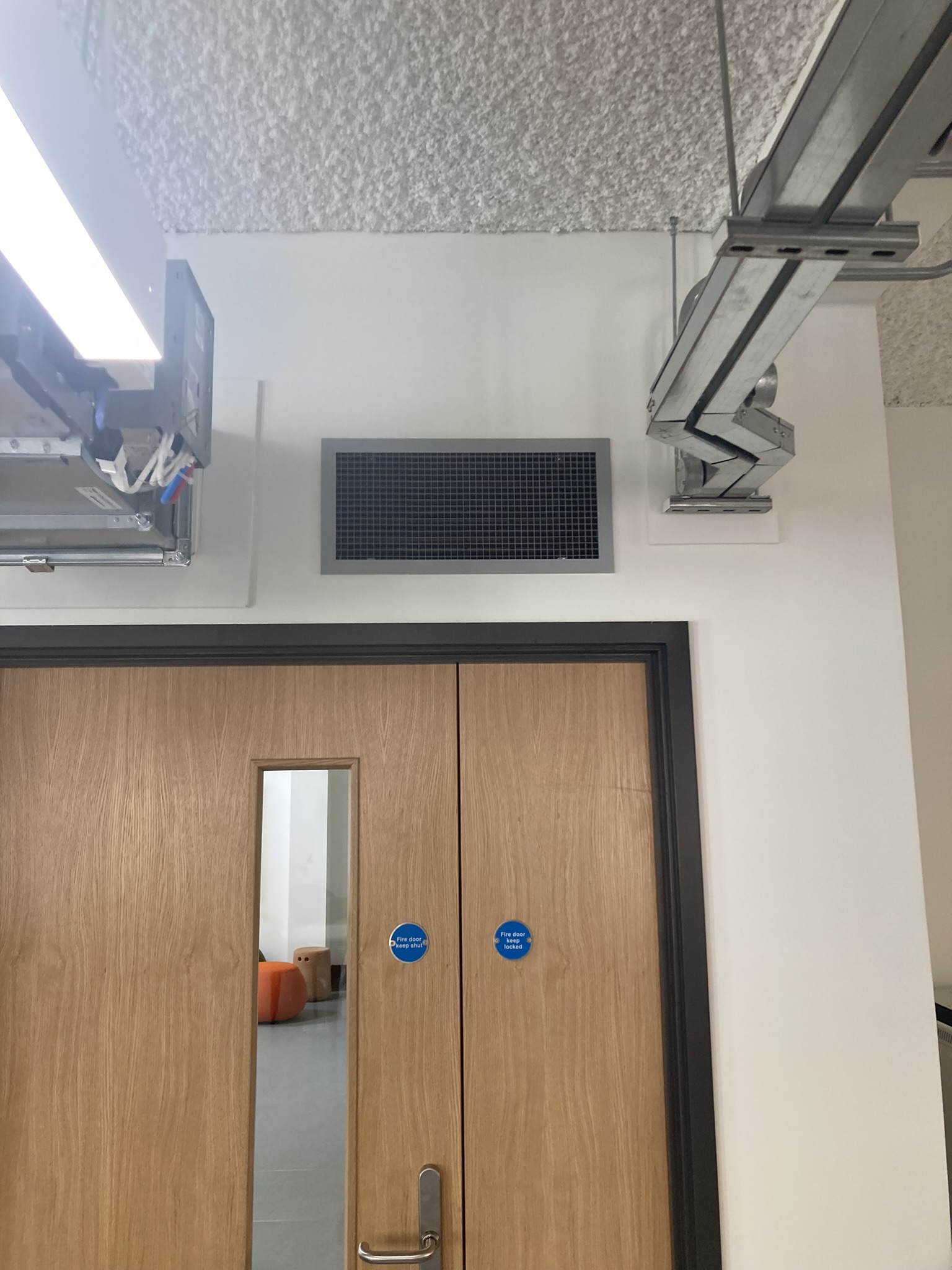
Solution pre-intervention: ExtractGrilles.JPEG.jpeg
Solution pre-intervention: IMG_3014.JPG.jpg
Solution pre-intervention: IMG_3015.JPG.jpg

Solution post-intervention

Solution post-intervention: Controller.JPEG.jpeg
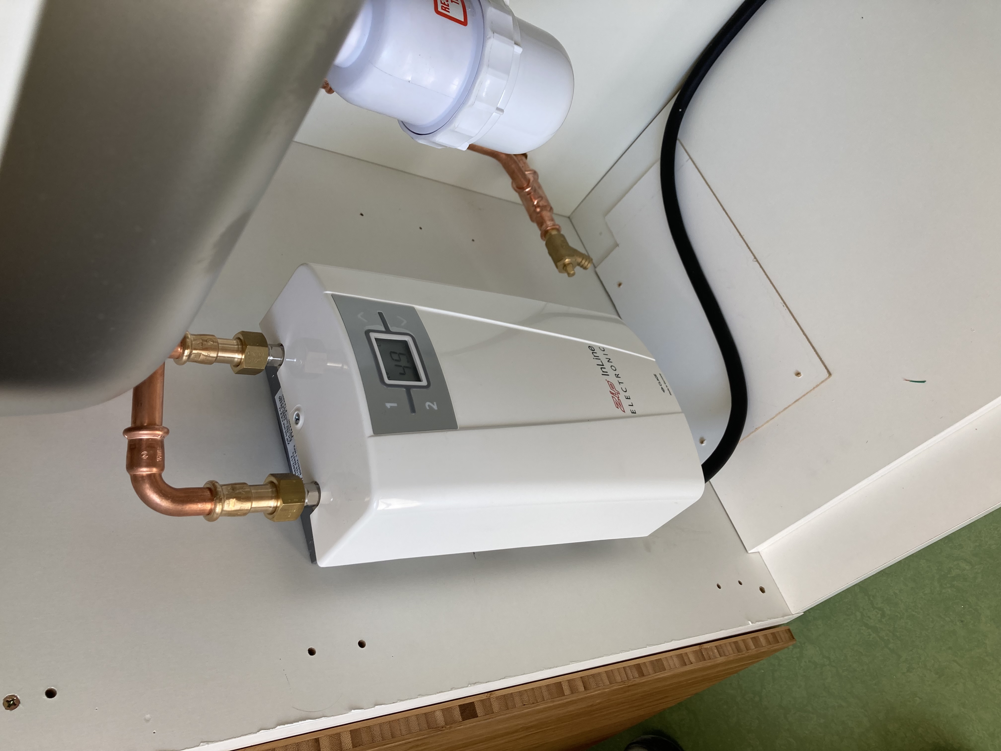
Solution post-intervention: HotWater1.JPG.jpg
Solution post-intervention: HotWater2.JPG.jpg
Solution post-intervention: IMG_3012.JPG.jpg
Solution post-intervention: IMG_3018.JPG.jpg
Solution post-intervention: IMG_6089.jpeg
Solution post-intervention: IMG_8308.jpeg
What is the Solution?

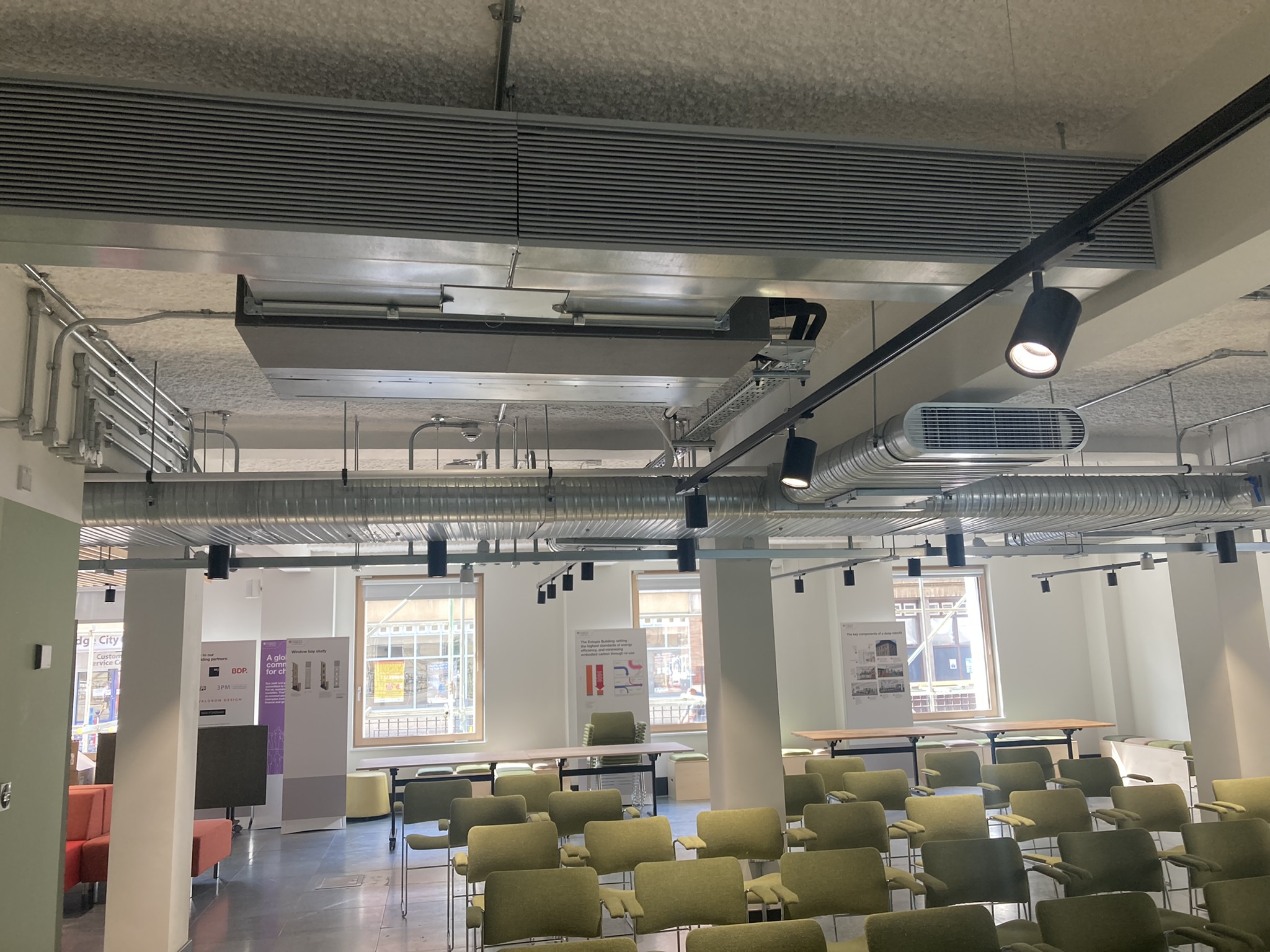
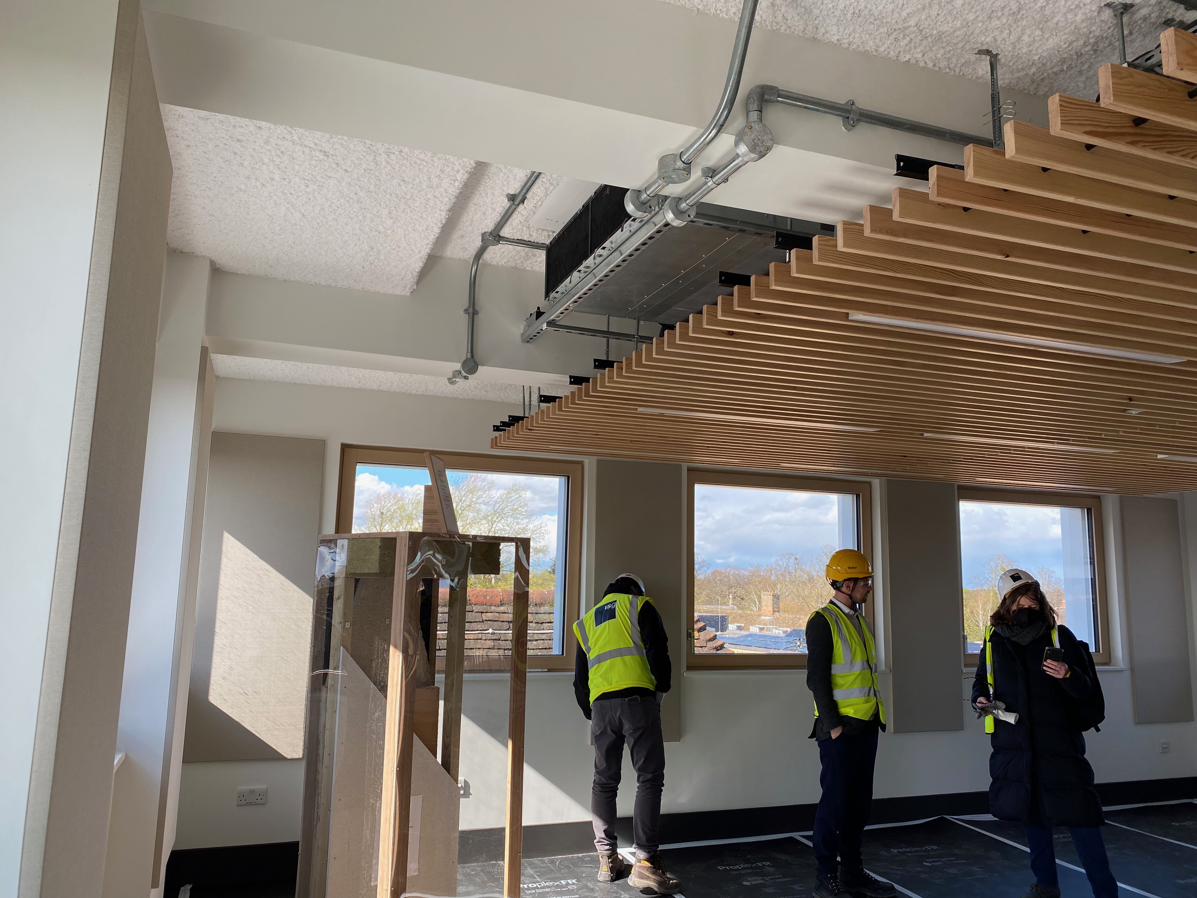
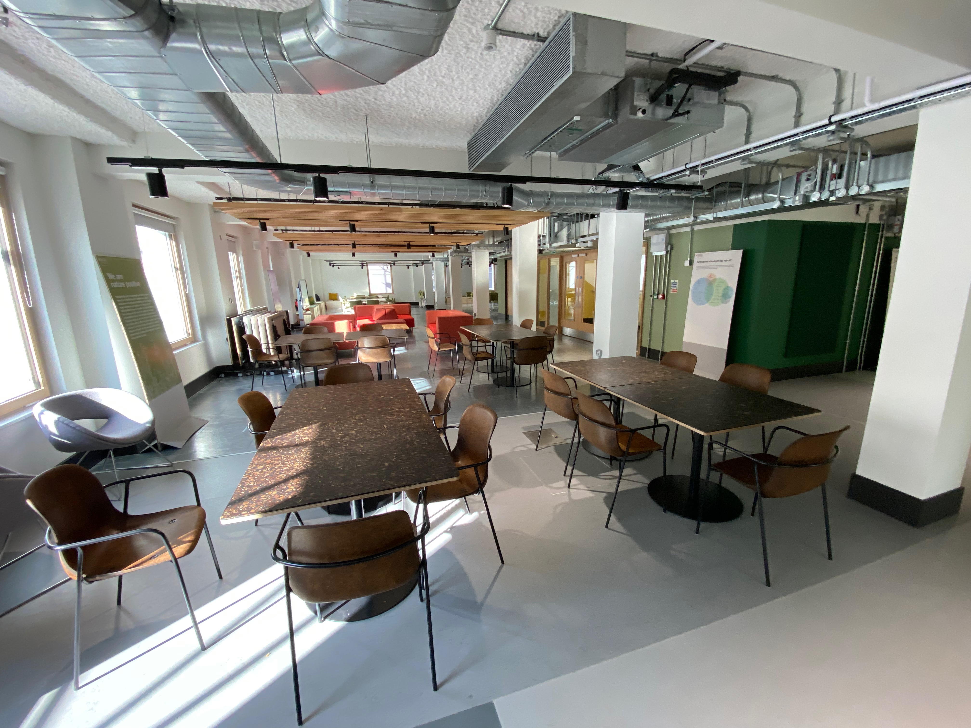
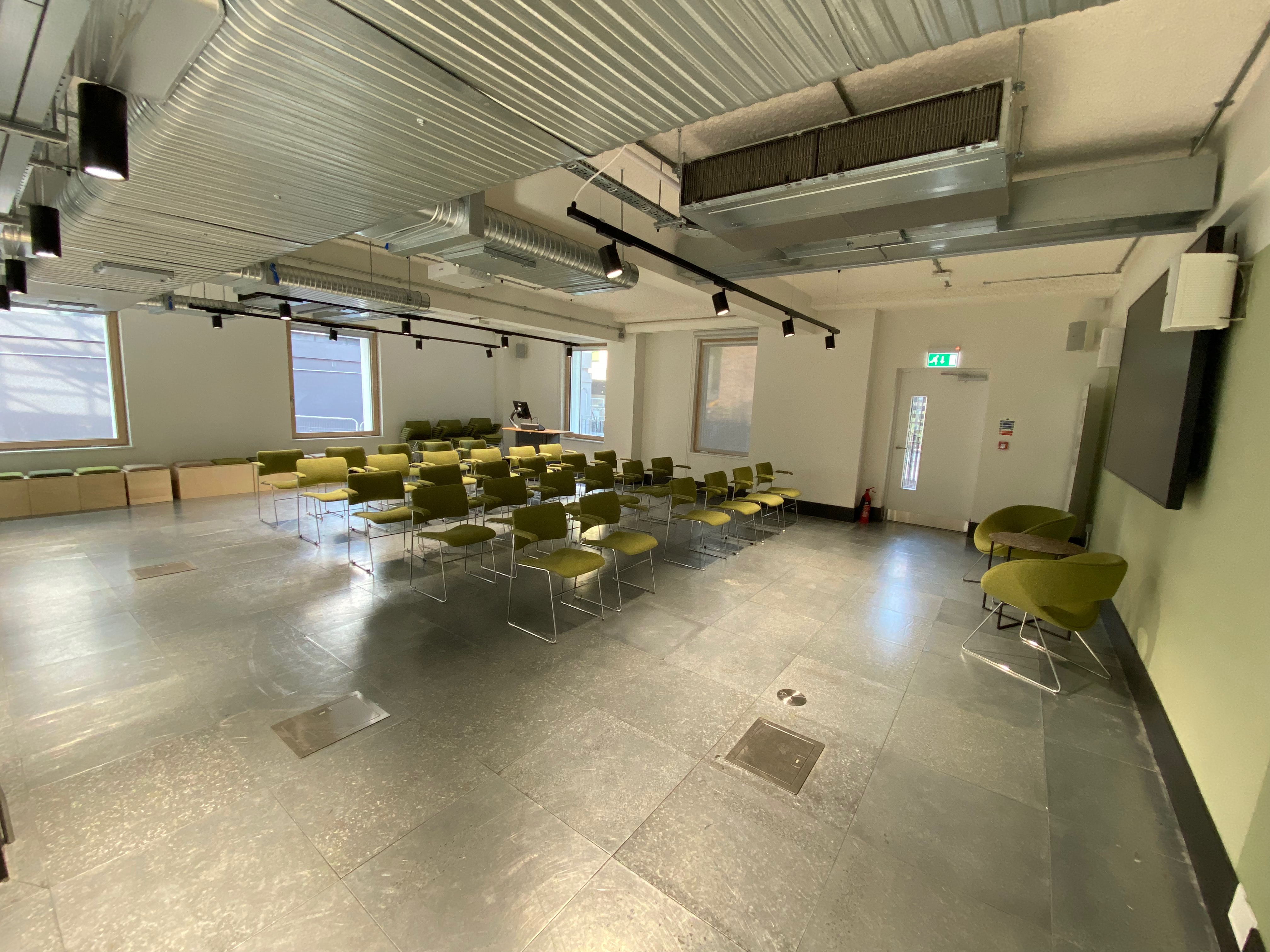
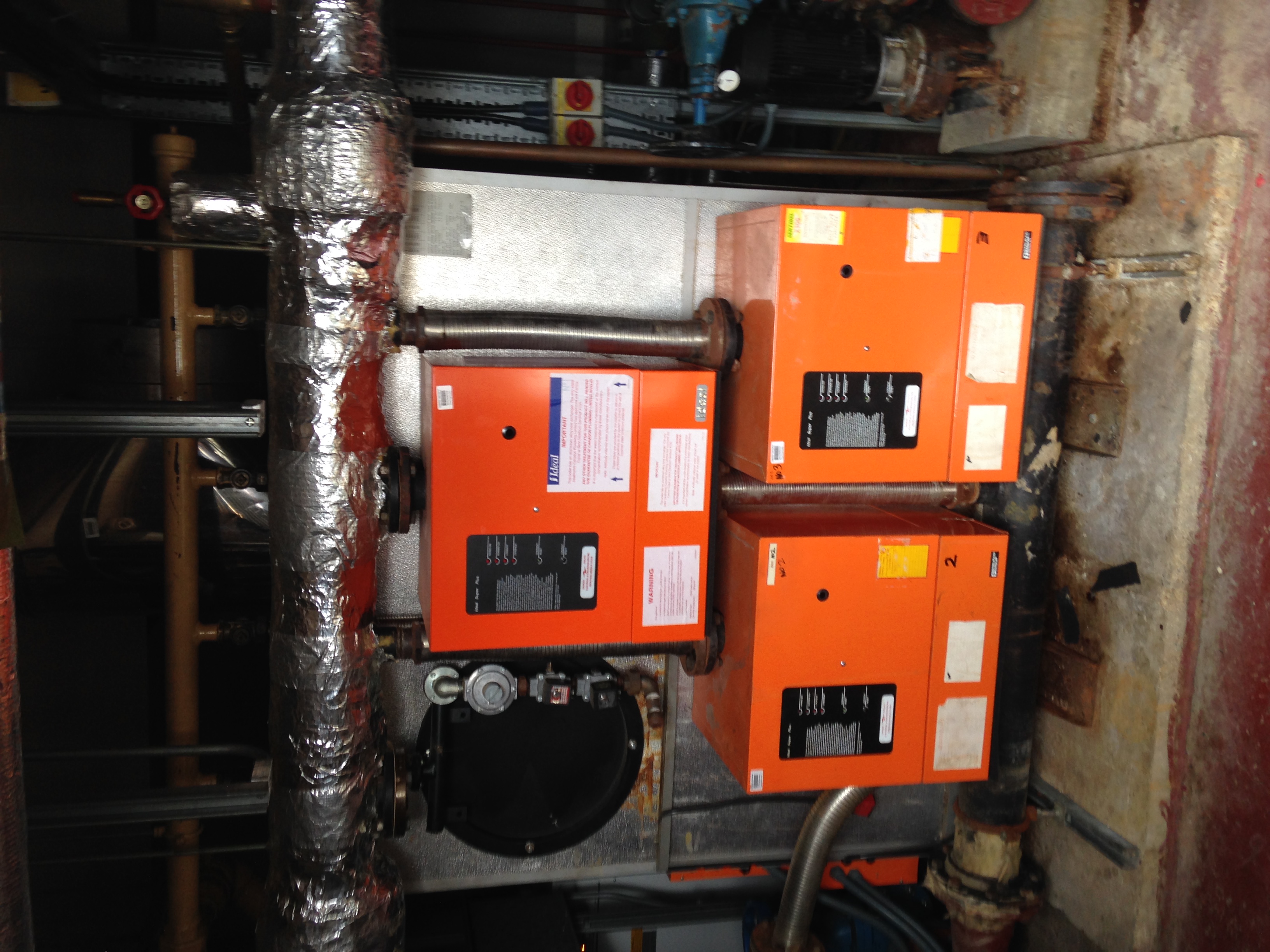
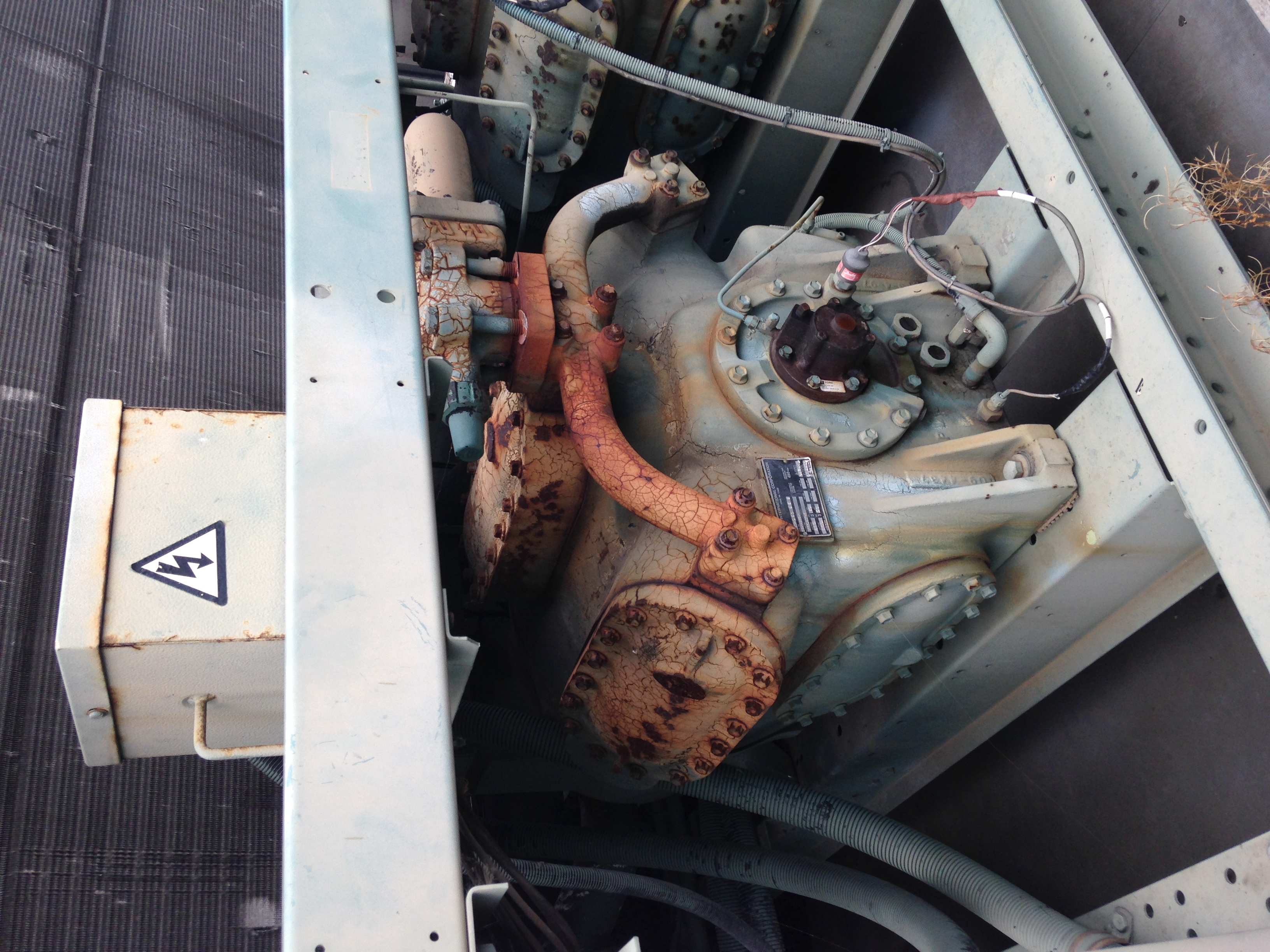
The previous ventilation systems consisted of a roof mounted supply ventilation AHU, served by a LTHW frost coil and a post heating coil to temper incoming fresh air. Fresh air is ducted to the core risers and drops vertically to serve each level of the building. On each floor level horizontal ductwork branches from the main vertical riser at high level, then running within ceiling voids and bulkheads to serve supply grilles and diffusers. Extract ductwork (Bellmouth) located around the buildings core, draws extract air back to the riser and back up through building to a roof mounted extract fan which. The WC’s / Toilet Cores are each fitted with a local extract fans located within the ceiling void. Extract ductwork in the toilet cores connects to the fan about the celling voids, exhaust air is connects to the internal/external walls via a louvre.

Why Does it work?

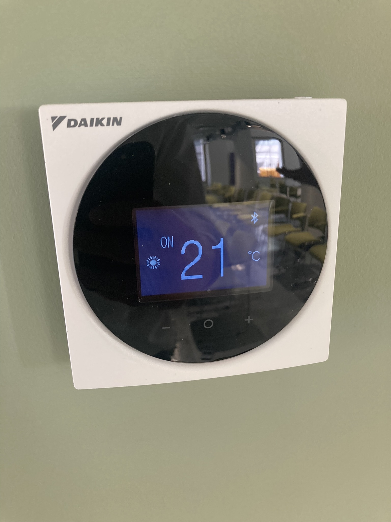
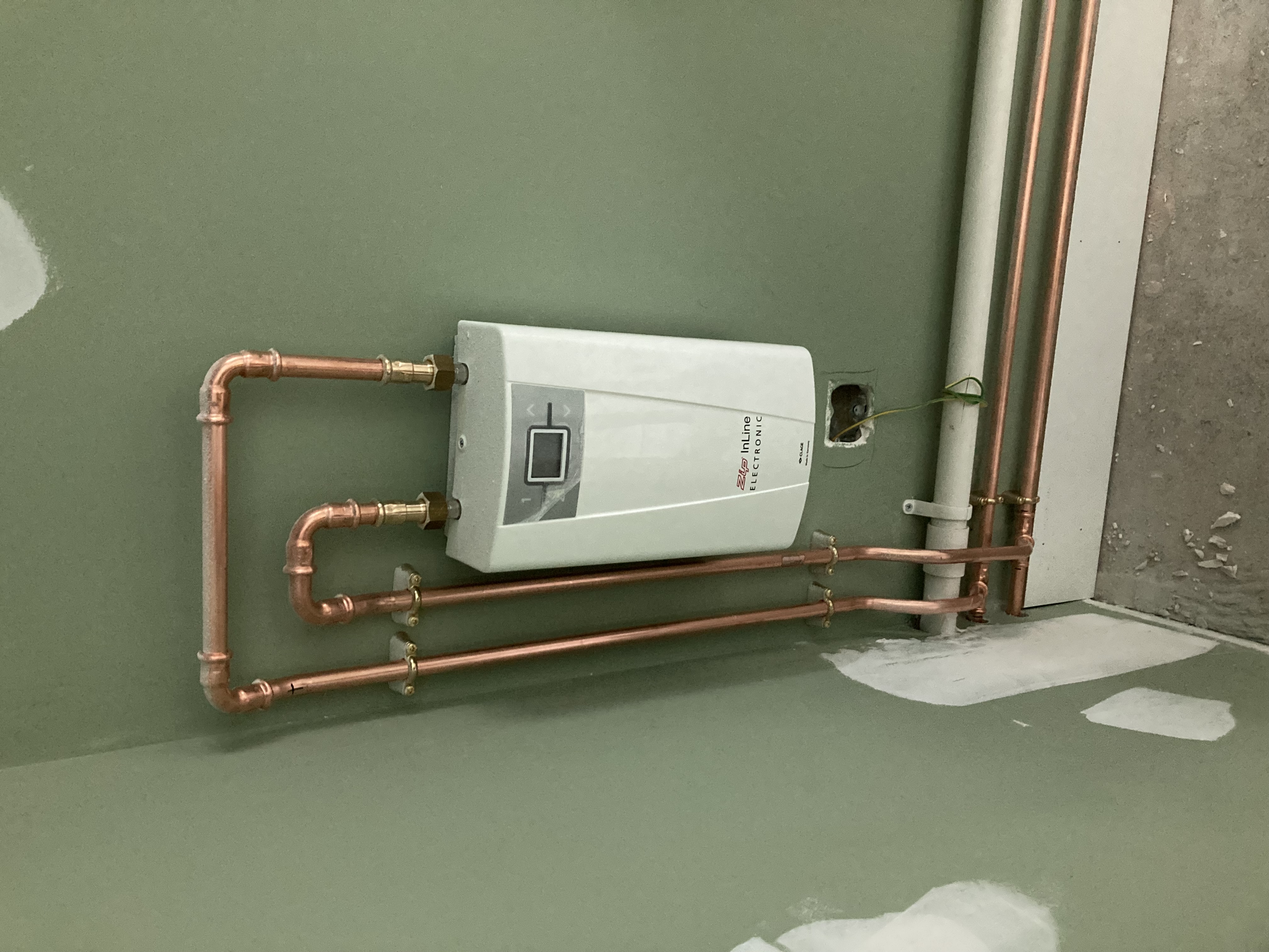
MEP provision was considered carefully to maximise efficiency and performance. The fabric first approach allowed electrical capacity requirements to remain at pre-refurbishment levels, despite the switch to all electric heating. This avoided the high-cost risk associated with requiring more power capacity from the regional electrical distribution network operator. This was also valuable as it avoided the requirement for a new electrical transformer, for which little space was available on the site. The high performance of the building fabric allows thermal comfort to be maintained with MVHR ventilation and minimal active heating or cooling, including fewer local radiators and fan coil units relative to conventional buildings. Coupled with energy efficient Heating, Ventilation and Air Conditioning (HVAC) specifications, this reduces the amount of energy (and therefore carbon emissions) required to maintain thermal comfort and allows smaller MEP equipment – and less equipment overall (for instance, fewer local radiators and fan coil units) – to be used, this, in turn, reduces the building’s whole life embodied carbon. They designed ventilation ducting to maximise the floor-to-ceiling height in office areas and allow larger ceiling heights than the building afforded prior to refurbishment. Services design included point-of-use tankless water heaters to reduce heat loss from distributing water from a central plant, plus the provision of zip taps to replace kettles at tea points, which were researched to be more efficient based on consideration of likely occupant behaviour.

PROS
  • 1. Fabric-first approach: The extensive insulation and airtightness improvements reduce heating/cooling demand, allowing for smaller HVAC systems.
  • 2. All-electric systems: Removal of gas boilers and switch to air source heat pumps and electric point-of-use water heaters reduces carbon emissions.
  • 3. Heat recovery ventilation: The mechanical ventilation with heat recovery (MVHR) system improves energy efficiency while providing good indoor air quality.
  • 4. Demand-controlled ventilation: CO2 and temperature sensors allow for optimised airflow, improving efficiency and comfort.
  • 5. Passive cooling strategies: Night purge ventilation and exposed thermal mass help reduce cooling loads.
  • 6. Retaining and reusing some existing elements: Some electrical infrastructure and ventilation risers were kept, reducing embodied carbon.
CONS
  • 1. Complexity: The multiple systems and controls may be more complex to operate and maintain compared to the original simpler systems.
  • 2. Potential moisture risks: Internal wall insulation can create interstitial condensation risks if not detailed carefully. The case study mentions WUFI analysis was needed.
  • 3. Heritage impact: Some original features like windows were altered, which may impact the building's historic character.
  • 4. Occupant adjustment: Users may need time to adapt to new systems like MVHR and demand-controlled ventilation.
  • 5. Higher upfront costs: While lifecycle costs may be lower, the initial investment in high-performance systems is likely higher.
  • 6. Reliance on electricity grid: The all-electric approach means the building is more vulnerable to power outages.
  • This analysis balances energy efficiency and comfort improvements against potential heritage, cost, and operational considerations.
Heating nominal power
information not available
Heating efficiency
information not available
DHW nominal power
information not available
DHW efficiency
information not available
Cooling unit
Heat Pump
Cooling centralized/decentralized
Centralized
Cooling distribution system
Air
Cooling supply
Air outlets
Cooling nominal power
information not available
Cooling efficiency
information not available
Ventilation type
Balanced Mechanical Ventilation
Ventilation centralized/decentralized
Centralized
Heat recovery efficiency
information not available
SFP if relevant
information not available
Technical drawings

Before retrofit

After retrofit

Before retrofit
Heat generator
Boiler (non condensing)
After retrofit
Heat generator
Heat Pump
Before retrofit
Fuel type
Gas
After retrofit
Fuel type
Electricity
Before retrofit
Centralized/Decentralized
Centralized
After retrofit
Centralized/Decentralized
Centralized
Before retrofit
Distribution system
Water
After retrofit
Distribution system
Air
Before retrofit
Heating supply
Radiators
After retrofit
Heating supply
Air outlets
Before retrofit
DHW same as heating system
no
After retrofit
DHW same as heating system
yes
Before retrofit
DHW heat generator
information not available
After retrofit
DHW heat generator
information not available
Before retrofit
DHW fuel type
information not available
After retrofit
DHW fuel type
information not available
Before retrofit
DHW centralized/decentralized
Centralized
After retrofit
DHW centralized/decentralized
information not available

Assessment

Heating
Yes
Cooling
Yes
Ventilation
Yes
Heat generator
Heat Pump
Heating centralized/decentralized
Centralized (multi family house/non residential)
Heat supply
Air outlets
Heating existing distribution system
No
Circular approach - heating
No
Investment cost - heating
High
Cooling generator
Chiller
Cooling generator (Additional info)
Centralized (multi family house/non residential)
Cooling supply
Air outlets
Circular approach - cooling
No
Investment cost - cooling
High
Ventilaiton strategy
Mechanical Ventilation System
ventilation centralized/decentralized
Centralized (multi family house/non residential)
Heat recovery
No
Circular approach - ventilation
No
Investment cost - ventilation
High

Location

Cambridge, United Kingdom - 6m
Climatic Zone:Cfb